
Pulsed Electromagnetic Field (PEMF) technology delivers low-frequency electromagnetic pulses to the body. Modeled on natural planetary frequencies—most notably the 7.83 Hz Schumann resonance—PEMF stimulates cellular transmembrane potential, promotes ion displacement across cell walls, and supports natural tissue recovery.
Inside an authentic PEMF wellness mat, the emission system relies on three synchronized components:
- The Pulse Generator (MCU & Driver Circuit): Converts input power into high-speed, controlled pulses characterized by specific frequencies, waveforms, and sharp duty cycles.
- The Pure Copper Emission Coils: Flat, tightly wound pancake coils acting as electromagnetic radiators, transforming rapid electric current spikes into localized magnetic pulses.
- Bio-Inductive Coupling: As the magnetic waves travel through the mat’s layers into soft tissue and bone, they induce microcurrents ($dB/dt$) across cell membranes, activating mitochondrial ATP synthesis and optimizing local microcirculation.
Hardware Anatomy: What Inside a PEMF Emission System Really Matters?
The performance of a PEMF mat is governed by its internal driver topology and coil engineering rather than exterior upholstery:
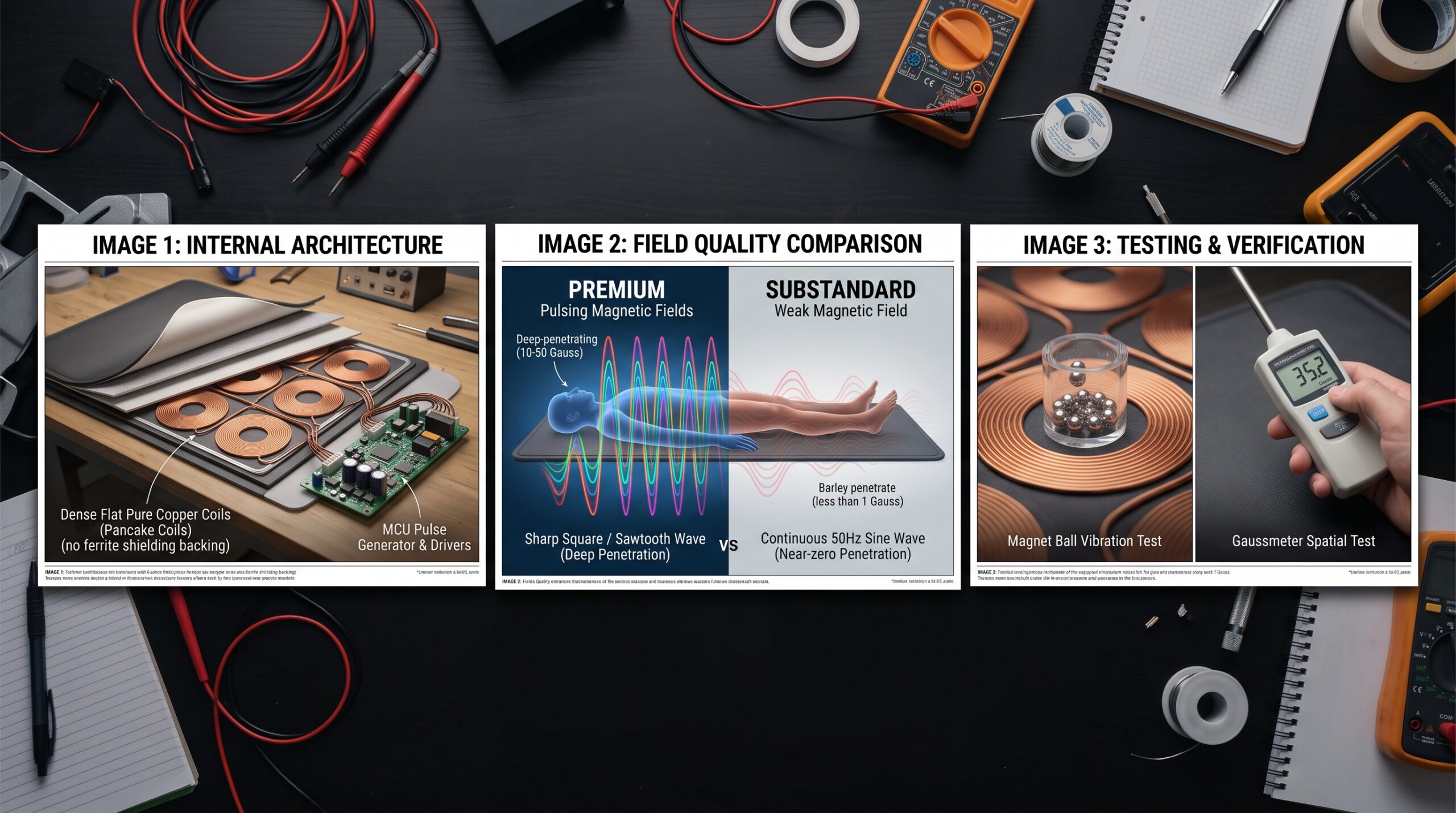
- Pancake Coil Design: Built from high-grade enameled pure copper wire. Crucially, these coils must not carry the high-frequency ferrite shielding plates typical of Qi wireless chargers. Ferrite backing traps and confines magnetic flux within a tight surface boundary, which prevents the open-field spatial radiation necessary for deep bodily penetration.
- Rapid-Switching Power Electronics: High-speed MOSFETs or IGBTs driven by microcontroller units deliver ultra-sharp rising edges (nanosecond to microsecond rise times), creating steep rates of change in the magnetic field.
- Thermal Isolation & Enameling: Far-infrared therapy mats typically generate surface heat between 50°C and 70°C. Quality PEMF coils utilize copper wire rated for 130°C to 180°C alongside flame-retardant encapsulation to prevent insulation breakdown under continuous thermal cycling.
Technical Benchmarks: Separating Legitimate PEMF from Inferior Designs
Evaluating the therapeutic value and build quality of a PEMF mat involves five core criteria:
1. Pulse Waveform and Rise Time ($dB/dt$)
- Substandard Units: Utilize smoothed, continuous sine waves derived from step-down 50/60 Hz mains power or slugged switching circuits. A gradual slope lacks the acceleration needed to induce biological microcurrents across cellular lipid bilayers.
- Medical-Grade / Premium Units: Deploy rapid square waves, rectangular pulses, or sawtooth waveforms. A virtually vertical rising edge maximizes field variation over time ($\frac{dB}{dt}$), which drives effective cellular membrane depolarization.
2. Flux Density and Spatial Penetration (Gauss / Microtesla)
- Substandard Units: Underpowered coils built with thin wire gauge yield surface readings below 1 Gauss after penetrating gemstone composites, foam padding, and leatherette layers. The field fades completely before reaching deeper musculature.
- Premium Units: Deliver calibrated surface flux density between 10 and 50+ Gauss (1 Gauss = 100 $\mu T$). This ensures ample field strength to pass through multi-layer thermal barriers and deliver therapeutic flux deep into joints and soft tissue.
3. Frequency Versatility vs. Single-Frequency Limits
- Substandard Units: Locked to a single arbitrary frequency without options for protocol adjustment.
- Premium Units: Feature multi-stage frequency programs spanning the 1–30 Hz window. This range targets distinct restorative states: Delta band (1–4 Hz) for deep sleep induction, Schumann resonance (7.83–8 Hz) for autonomic balancing, and Beta band (12–20 Hz) for physical activation.
4. EMI Management and Electrical Decoupling
- Substandard Units: Poor circuit isolation between AC heating elements and DC pulse drivers, leading to high-frequency electromagnetic noise, audible coil whine, and uncontrolled electric field bleed.
- Premium Units: Separate wiring architectures pairing non-inductive, shielded heating cables with dedicated low-noise PEMF drive lines. The heating and electromagnetic functions operate independently without electrical interference.
5. Array Geometry and Torso Coverage
- Substandard Units: Feature only 1 or 2 isolated coils hidden inside a full-sized mat, leaving wide dead zones across the treatment surface.
- Premium Units: Array 4 to 8 strategically spaced coils across the length of the mat, providing continuous, targeted coverage from the cervical spine down to the lower extremities.
Workshop & Field Inspection Methods
Evaluating coil performance and field integrity requires three reliable testing procedures:
- Magnet-Tester Ball Vibration Test: Place a floating magnetic test cylinder or neodymium indicator disc directly over the marked coil zones. Upon engaging the program, an authentic pulsed field causes the magnet to vibrate with distinct, crisp acoustic and visual oscillations that mirror the set frequency. Inactive or continuous-wave fields produce no movement.
- Gaussmeter Distance Gradient Test: Place a calibrated Hall-effect Gaussmeter probe flush against the mat surface to log the baseline peak reading, then raise it 5 to 10 centimeters vertically. A high-efficiency coil maintains a gradual attenuation curve, retaining several Gauss of magnetic flux at depth.
- Oscilloscope Induction Pickup: Position a small passive copper pickup coil over the mat surface and connect it to a digital oscilloscope. Legitimate PEMF hardware reveals clean square or pulsed waveforms with sharp, vertical transitions, whereas substandard circuits display distorted, rounded AC noise.